01 / Industrial Product Communication · Peroni Pompe

From Engineering Complexity to Customer Clarity

I transformed complex high-pressure pump engineering into a reusable visual communication system for product pages, technical sales, Factory Acceptance Tests, service communication, and international exhibitions.

Across selected Peroni Pompe work

  • 30+Renderings
  • 10+Animations
  • 5+Customized Projects
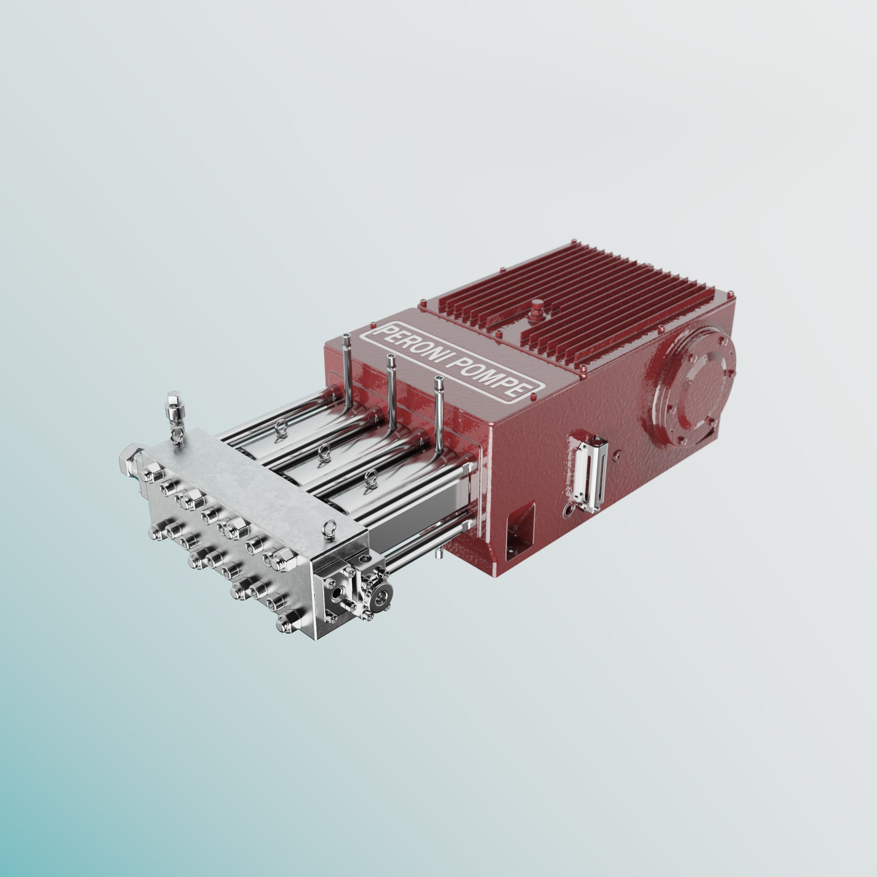
Photorealistic customer-facing rendering of a Peroni Pompe industrial plunger pump
Final customer-facing render · Product pages / Technical sales / Exhibitions
Role
Product Visualization DesignerOwned visualization execution from supplied CAD through animation, rendering, and post-production
Timeline
Core case: Autumn 2025 · Selected professional outputs: 2025–2026
Core Tools
SolidWorks, KeyShot, Blender, Premiere Pro, After Effects
Deliverables
Renderings, 360° viewers, technical animations, catalogues, presentations, and exhibition assets

01 / Context & Challenge

Static CAD and verbal explanations could not serve every customer-facing audience.

Industrial Context

High-pressure pumps for critical, application-specific conditions

Peroni Pompe manufactures API-compliant plunger, diaphragm, metering, and steam-driven pumps for process industries. Standard power ends are combined with liquid ends, valves, seals, materials, and unit arrangements selected for each application.

Communication Challenge

Accurate drawings and verbal explanations were not intuitive for every stakeholder.

Marketing requested a film for customers, prospects, and non-engineering departments inside client organisations. My role was to preserve the technical logic while using viewpoint, colour, motion, and information depth to make the operating principle easier to understand.

Aerial view of the Peroni Pompe manufacturing facility
Manufacturing context. Public image from Peroni Pompe ↗
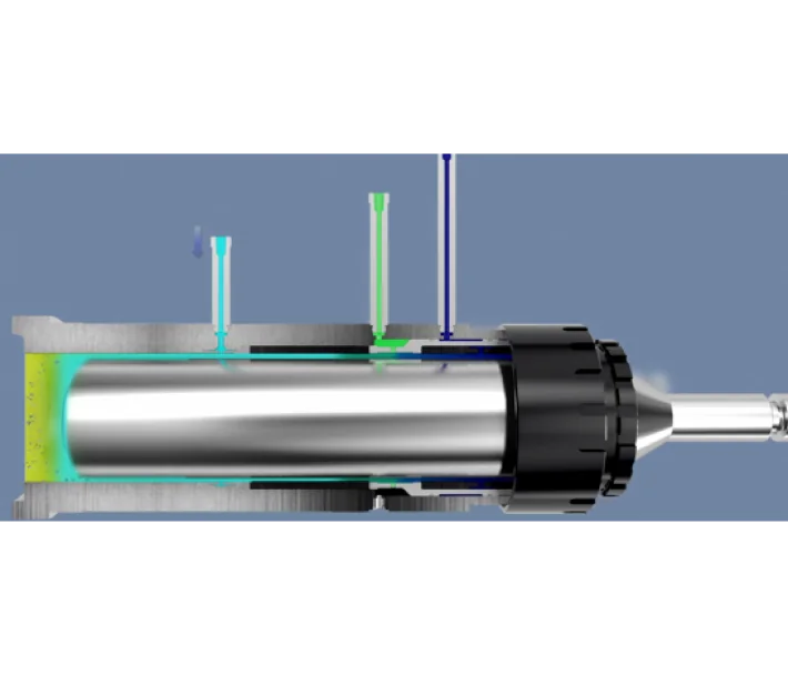
Public cutaway showing the internal construction of a pump liquid end
A liquid end contains relationships that an exterior view cannot explain. Public image from Peroni Pompe ↗

02 / My Role & Workflow

Five decisions behind every approved visualization.

  1. 01

    CAD Preparation & Privacy

    In SolidWorks I add visible liquid or gas volumes, rebuild missing presentation details, remove non-operational hooks or service parts, and simplify confidential geometry.

    Decision Show function without exposing unnecessary engineering detail.

  2. 02

    CMF & Camera

    I compare render materials with physical samples and manufactured finishes, then choose the viewpoint that makes interfaces and hierarchy easiest to read.

    Decision Accuracy and legibility before visual polish.

  3. 03

    Flow & Timing

    Stroke, valve timing, and flow direction are structured from engineer briefings, factory observation, and protected sectional drawings.

    Decision Turn operating logic into a readable sequence.

  4. 04

    Three Review Gates

    I validate CMF, review critical keyframes, and approve a low-resolution video preview before committing to batch rendering.

    Decision Correct expensive errors before final output.

  5. 05

    Post-production & Delivery

    Approved sequences are rendered in batches, then edited in Premiere Pro and After Effects with branding, explanatory text, and required visual effects.

    Decision Adapt one verified technical story to each channel.

Workflow Evidence

Decisions grounded in the physical product.

01 / Factory Observation

Operation before animation

I observed the pump's internal construction with engineers before defining stroke, valve timing, and flow.

Permanently blurred engineering drawing used as a protected technical referenceProtected reference

02 / Engineering Reference

Verify relationships and timing

Sectional drawings support component and sequence checks. All technical content shown here is permanently obscured.

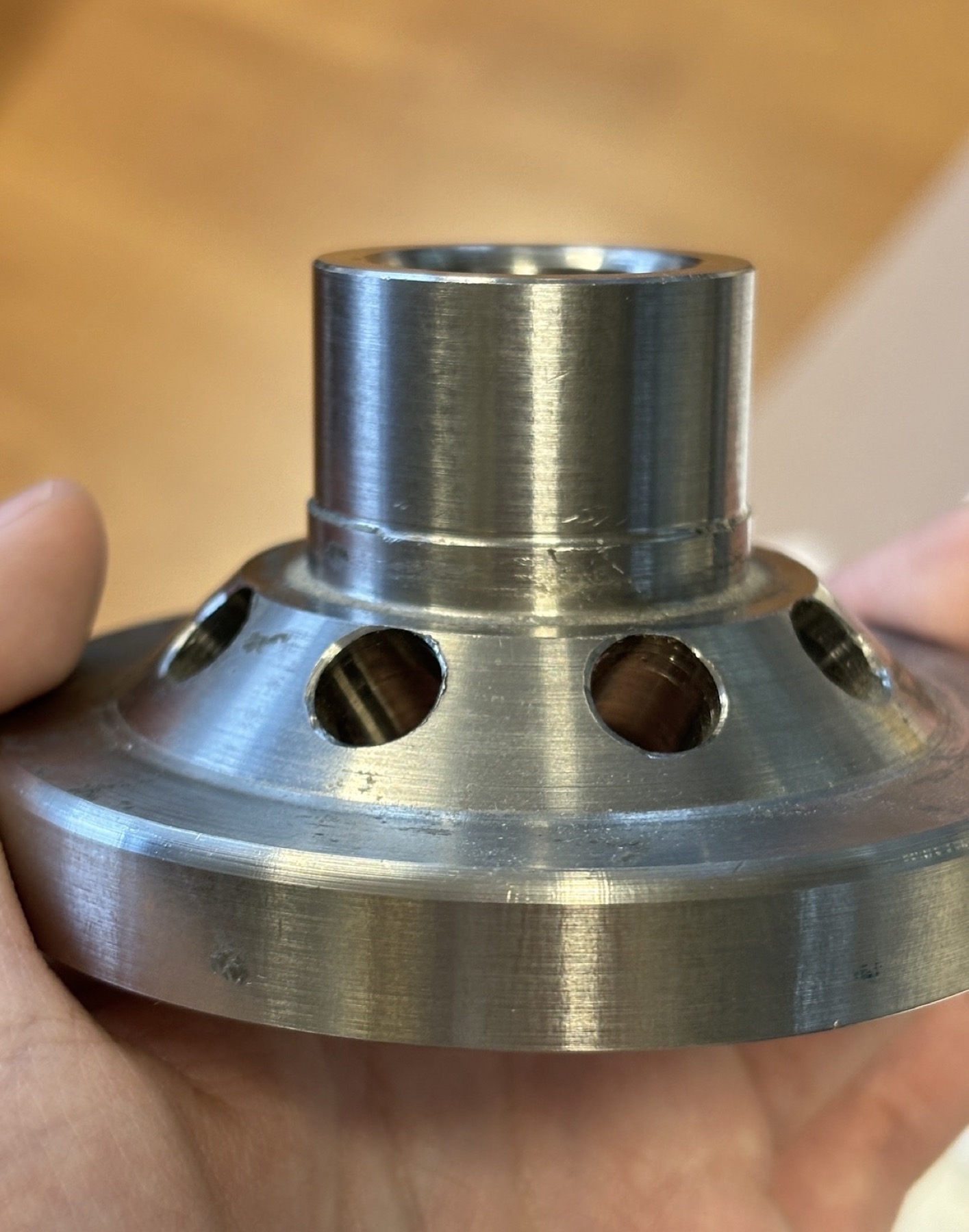
03 / Physical Validation

Match the digital model to reality

I compare machined finishes, painted texture, and lubrication conditions with the visualization.

03 / Best Visuals — Top Five

Five selected outcomes show the path from product inspection to customer application.

Visual 02 / Operating Principle

Dedalo® Seal Flow

A public technical animation showing progressive pressure reduction across the sealing rings and the return of residual process fluid to the pump suction line.

Section view / Pressure cues / Animation

Visual 03 / Component Logic

Axial Double-Port Valve

The exploded sequence reveals component hierarchy and assembly order without exposing the complete engineering model.

Exploded view / Component hierarchy / Animation

Visual 04 / Customised System

CO₂ Injection Pump System

A customer-facing presentation film combining controlled camera movement, 3D visualisation, and technical callouts for a customised pumping unit.

CAD optimisation / Rendering / Technical presentation
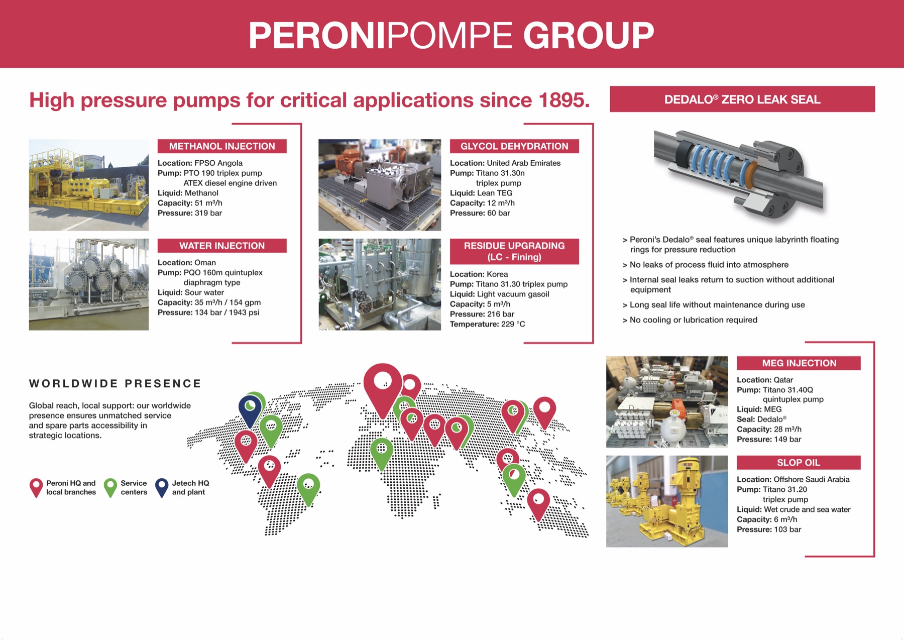
Peroni Pompe large-format product communication panel for ADIPEC 2025

Visual 05 / Final B2B Application

ADIPEC Exhibition Panel

Approved product renders and technical messages were adapted for rapid understanding at international exhibition scale.

Open the full panel PDF ↗

04 / Technical Deep Dive — 3130N Plunger Pump

Connecting product architecture, mechanical motion, and fluid behaviour.

The 3130N combines a power end, three reciprocating plunger assemblies, valve timing, and two fluid phases that cannot be understood from the exterior alone. I structured one sequence that moves from product construction to the operating principle without losing the engineering relationships.

  • Product architecture
  • Mechanical motion
  • Valve & flow timing
  • Customer film
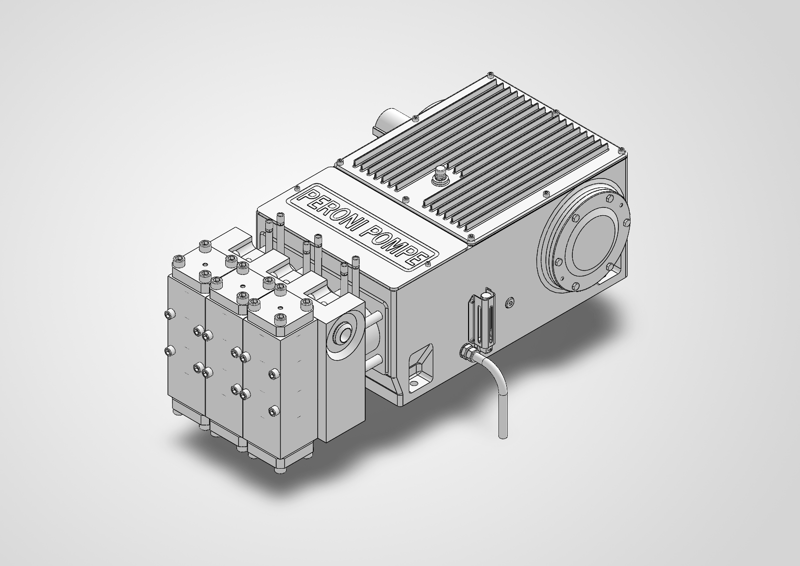
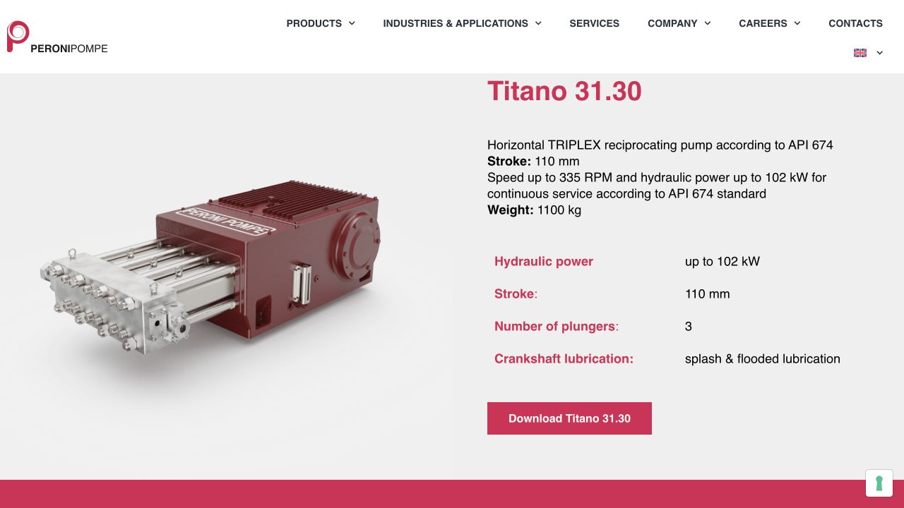
SolidWorks CAD view of the complete 3130N plunger pump before visualization preparation Power end & product envelope retained Liquid-end interfaces preserved

01 / Engineering Input

Reduce CAD complexity without breaking the system.

The SolidWorks input established the complete product envelope, power-end and liquid-end interfaces, service features, and external presentation geometry. I removed non-operational details, rebuilt missing presentation elements, and controlled the disclosure depth before developing the internal operating sequence.

What could change Presentation detail, removable parts, and disclosure depth.
What could not change Axes, interfaces, component order, and mechanical continuity.

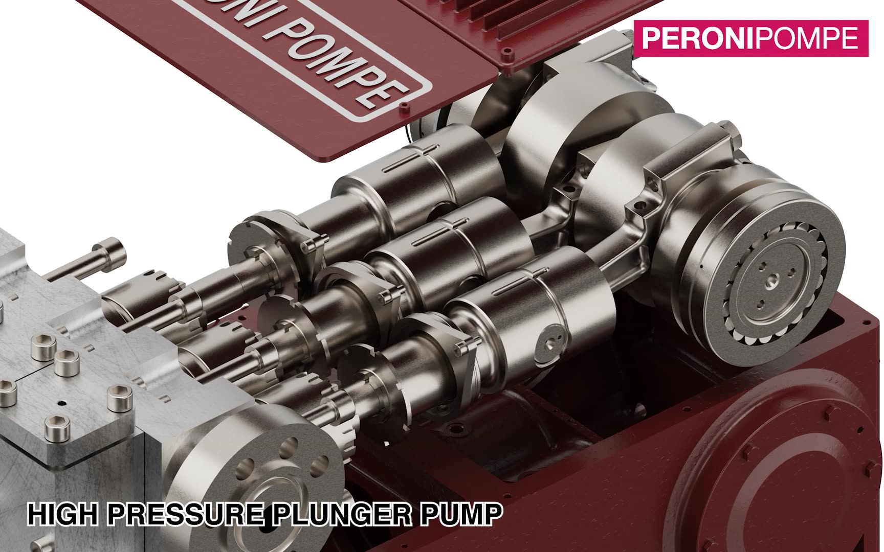
3130N power end shown in close view with crankshaft, connecting rods, and three plunger axes visible Crank rotation becomes the starting cue Three motion paths stay comparable

02 / Communication Decision

Reveal the mechanism before explaining the flow.

The sequence first separates the major assemblies, then reveals the crank mechanism and three plunger paths before moving into the liquid-end section. This progression gives the viewer a spatial model first, so later valve and flow changes have a clear mechanical cause.

Design principle Establish where motion comes from before asking the viewer to interpret hydraulic timing.

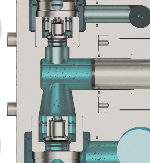
3130N liquid-end keyframe showing the cyan suction phase and corresponding valve state
Suction phase · Cyan
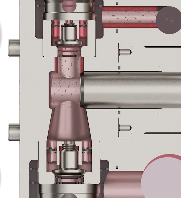
3130N liquid-end keyframe showing the magenta discharge phase and corresponding valve state
Discharge phase · Magenta

03 / Engineering Verification

Check motion, valve state, and flow as one timeline.

Reviews were conducted verbally with engineers and focused on incomplete detail visibility, fluid colour and representation, and critical coordination points such as valve opening and closing in relation to plunger motion. I exported keyframes and a low-resolution preview to resolve those issues before batch rendering.

  1. Gate 01Geometry & CMFDetail visibility, material identity, and disclosure level
  2. Gate 02Critical keyframesValve state, plunger position, and corresponding fluid direction
  3. Gate 03Preview approvalFluid colour, timing, camera sequence, and explanatory rhythm

04 / Final Customer Output

One film moves from product construction to operating principle.

Peroni Pompe supplied the base model; I independently completed the CAD preparation, visual direction, animation, rendering, and post-production. Marketing defined the brand copy and publication channels. Produced without agency involvement, the approved film was published on the official website and LinkedIn.

  • Architecture connects to internal motion
  • Cyan and magenta separate the two fluid phases
  • One verified timeline supports technical explanation

05 / Engineering Collaboration

From public technical reference to an approved customer explanation.

Before — public dimensional references establish the product envelope, interfaces, and typical unit arrangement. The drawings rotate automatically; select the image to view it at full size.
3130N liquid-end section showing the cyan suction phaseView the 3130N deep dive ↑
After — the approved 3130N animation connects crankshaft rotation, plunger motion, valve timing, and fluid flow. The complete film and decision breakdown are shown above.
Disclosure Boundary

The drawings and animation shown here are public examples. Customer-specific CAD, specifications, identities, and unapproved review material remain offline.

06 / Scope, Adoption & Reach

Verified production scope and real-world deployment.

Production Scope

30+

Customer-facing renders in a reusable industrial product library

10+

Technical animations covering operation, assembly, and maintenance

5+

Customer-specific engineering communication projects supported

4

International exhibitions using adapted approved assets

2

FATs supported with technical communication

Deployment & Reach

Work that moved beyond delivery and into real customer touchpoints.

Official Adoption Live

Official website technical content

Selected visualisations were published on official product pages as customer-facing technical explanation assets.

Platform Reach 5K+

Official LinkedIn publication

Individual posts consistently reached more than 5,000 views. The supplied 3130N post capture recorded 84 reactions, 3 comments, and 13 reposts.

View the official 3130N post ↗
B2B Engagement B2B

A shared explanation across departments

Public and exhibition use gave customers, prospects, and non-engineering stakeholders inside client companies a common visual reference for technical discussion.